| Tell me when this page is updated |
Tripod powered by Cable & Wireless
| Tell me when this page is updated |
The Airfix Suffolk kit, while being innacurate in many ways, is solid enough to form the basis of a collection of British and Australian cruisers of the "County" type. This was a large class of vessels, and while they did vary greatly in details large and small, it is feasible to build many of them - with varying degrees of difficulty - from the Airfix kit.
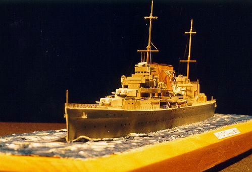
HMSs Suffolk and Cumberland were similar in that they both had their quarter decks cut down during refits in the late thirties. This is how Airfix have represented their kit and this makes Cumberland an obvious first choice for a conversion project. I have chosen to model Cumberland as she was sometime between this late thirties refit an the start of the Second World War, and in a China Station paint scheme. I like to make vessels in pre war configurations precisely because its possible to do light grey and white colour schemes along with varnished boats etc.
I have not yet completed my Cumberland and will write as I go. First, I will cover corrections and modifications to the hull.
The Hull:
The hull of the Airfix Suffolk is best described as "a bit dodgy". The bulges
are poorly represented as is the distinctive British cruiser "knuckle" in the bows. I started the
conversion by cutting the hull through about 2mm below the marked waterline so as to make a
waterline model. This is the most expedient way of dealing with the hull's problems. To do this
lay some sticky tape where you want to make the cut and use it much as you would a ruler to
guide a scriber along the plastic. Start out with very light strokes until a groove is established,
and then continue to work with heavier strokes until you are all the way through the hull
mouldings. I assembled and let dry the hull before I made these cuts. This makes the cutting a
little more difficult but has benefits later on.
When the hull and deck assembly has dried the cut at the waterline must be sanded flat on a stationary piece of wet and dry paper until it is smooth and even all round. When this has been achieved it will be necessary to glue strips of plastic card inside the hull and directly behind the bulges to back this area up when the bulges are scraped/sanded off. About two millimetres total thickness of added plastic card will be needed.
After this the hull can be glued down to a thickish sheet of plastic card and trimmed all round when dry. When trimming around the lower edge of the hull it will be hard to cut in very close to the after sections which curve rapidly under the vessel. This is good! This curve has been overstated by Airfix and it will be necessary to reshape it with putty. By leaving the sheet forming the bottom slightly proud in this area you can form a lip that will support the putty and allow you to shape a nicer hull section in this area. Reference to pictures of these ships will help greatly in getting this looking right.
Bulges
Removing the hull bulges is the next piece of major surgery required. While Cumberland like
Suffolk did have these bulges the representations on the Airfix kit are so poor that it is best to
remove them all together. Pictures do not show the bulges to have been very distinct, nor the
additional strake of armour that was fitted in the 30s. Both these structures were very close to the
waterline and as the model was to be set in a seascape where waves would obscure them, I
decided not to replace the bulges with more accurate ones or show the strake of armour. I may
well reverse this decision on later models however.
To remove the bulges start by carving them off moving the knife away from you until the bulk of the material has been removed. As you get closer to the hull sides use the knife as a scraper to shave the plastic away from the hull in small amounts. Finish with good quality sandpaper supported with a block and then fine grade wet and dry paper used wet and also supported with a block. At this stage all the final hull sanding can be completed. Next drill out all the scuttles with an appropriate sized bit held in a pin vise or motor tool if you have it. After drilling a final light sanding with very fine wet and dry paper to remove irregularities around the scuttles. With this done a start can be made on correcting the rather poorly moulded bow knuckle.
Bow Knuckle
The knuckle bow was a distinctive feature of almost all British cruisers and was meant to
maintain a useful flare but relieve the powerful upward forces on the entire bow structure when
plunging into a head sea.
To enhance the bow on this kit first cut two thin strips of plastic card a little longer that the
overall length of the knuckle and cement them in the position where the corner of the knuckle
should be on this ship. You will have to guess a little here and refer to photos and drawings if
you have them to get the strips (one each side) in the correct position. They should be a little
higher above the waterline forward than aft. When these are dry they can be used as a "dam" for
the filler that will be spread either side of the strip flush with the top of the hull and about 3mm
below the strip. Do the top section first allow it to dry and sand it smooth before doing the lower
side. Blend the rear and forward ends of the strips into the hull sides and bow respectively
checking sources to see how far aft the knuckle should extend.The lower side of the knuckle will
have to have a concave shape sanded in to represent the bow flare. Two applications of filler
may be required to get these surfaces sufficiently smooth. The sanding process will reveal the
scuttles drilled through earlier as tiny depressions and these can be drilled through again. Also,
the hawse holes will need to be drilled out as they will become obscured by the filler. finally,
The bow are on the kit has not the fineness that the real vessels had. By scraping and sanding the
areas immediately aft of the stem on either side a finer, more pleasing and realistic shape can be
obtained. This should complete work on the hull
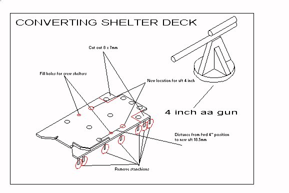
The shelter deck moulding on the Suffolk kit is innacurate and needs modifying as shown in the illustration here for both Suffolk and Cumberland. For Suffolk the kit supplied shelter for the 4" gun crews will have to be cut down the middle, each half shortened by about 4mm and joined back together. Cumberland as we are modelling her here had no shelters and these parts can be left off. The modifications are straight forward as can be seen from the diagram. The rear corners of the deck should be cur back as shown and the position for the after pair of 4" twin mountings moved forward to abreast the middle funnel. I have chosen to build Cumberland as she appeared before the second pair of 4" twins were added. Until this modification sometime around the beginning of the war she had a pair of single 4" in the forward position. These can be made up from plastic card and brass wire as shown in the diagram. Both wire and card are about .5mm thickness. The circular base is 3.5mm diameter and the central support is 3mm tall. The total length of the barrel piece is 7.5 mm and the piece on top is 3mm long. No doubt may modelers will find the design shown here not accurate enough for there tastes but when made up these items do look quite acceptable.
To make these discs I made up a punch and die from a small piece of scrap tinplate and a nail. Find a nail and drill bit that match in diameter, drill through the metal plate and ensure that the nail passes through. Take a small piece of thin wood or ply the same width as the metal plate and cut it in half. Now glue the smaller piece of ply (use super glue gel) onto the metal plate being sure not to cover the hole. Glue the large piece on top of this so it overhangs the hole. When dry pass the drill through the hole in the plate and drill through the top overhanging piece of ply . Now the hole in the ply should line up with the hole in the metal plate. Saw the pointed end off the nail to make a punch. Make sure the end is filled flat. You should be able to place a piece of plastic card between the metal plate and the top piece, place the nail through the hole in the ply and rest it against the plastic sheet. Support the entire thing on a few sheets of newspaper and tap the nail gently with a hammer. This should push out a disc of plastic the size of the hole.
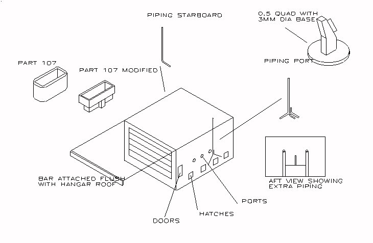
The drawing given here fully illustrates the modifications carried out on the Airfix hangar. The modifications shown are accurate for Suffolk as well. All that remains is to add photo etched railing around the top. The searchlight platform is easily modified from the kit part 107. After cutting the bottom half off, to be replaced with a plastic card structure as shown, run it across stationary sandpaper to reduce the wall thickness and sharpen the corners. The 0.5 quad machine guns are simply placed on plastic discs to represent a base plate and the kit supplied director and vent pipe are added according to the kit instructions. I used White Ensign Models doors and hatches on the hangar sides but good results could be achieved with squares of plastic card. The extra piping added at the rear side of the hangar was made from brass wire as was the prominent piping on the hangar sides. If this is carefully bent and the sawn ends filed smooth very good results can be achieved. I used .5mm wire for the port side and a finer size on starboard. Finally, add the bar across the top of the hangar doors. I don't know what it is there for but its in all the photographs I have seen.
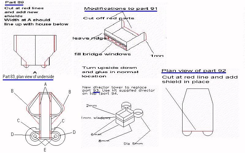
The bridge structure needs quite drastic modification to portray Cumberland. The first part that must be dealt with is part 83 (below). The drawing shows the necessary changes. The wings should be cut off and replaced with wider ones of a different shape (showed at "B"). On the kit these wings are represented as extending down to the deck below to for a triangular shaped house. This is not correct, they should extend out from a central rectangular house, created by fitting blanking pieces must be fitted at "A" and "C". There should be cruciform support structures made up from wire added under the wings. The circular surrounds at "D" should be cut away but the pins at "E" left so as to represent the supports for the pom-pom mounts. If this not done the 4 inch AA weapon will not fit in its proper place. All these modifications are necessary to make an accurate Suffolk as well. Airfix really got this part wrong!
The changes to part 89 are much simpler and are amply explained in the drawing below. New screens will have to be added to the cutaway areas. The cutaways at the narrow end must line up with the width of the house moulded below it. The cuts on the sides are made so as to make the whole thing a total of 2mm narrower than the kit part. That is, 1mm off each side.
The modifications to part 92 are simple and shown below. A new screen will have to be added at the wide end.
Part 91 represents the conning station. This was an open structure which sometimes carried a canvas roof. Airfix have represented this closed over. Quite an adequate fix can be made by turning the part upside down and making the modifications shown in the diagram below. I detailed mine with some voice pipes from wire, junction boxes, and a binnacle.
A new director tower must be made from plastic card as shown below. If you chose to make a wartime Cumberland the two "ears" at the rear have a single 20mm mounted in each. The kit supplied director can go on top.
 Assemble all these parts as per the kit instructions and you are done except for one thing. There
were pom-pom directors mounted each side of the bridge with the main body of the director
resting in a cutaway in the screens either side of part 89 and the trunk extending down to the
wings on part 83. Part 83 has to be widened as shown above to accommodate this. I made up
these directors from tiny lengths of coat hanger wire and plastic tube from the inside of a ball
point pen. The top was domed over with Blu-Tack to simulate the canvas covers.
Assemble all these parts as per the kit instructions and you are done except for one thing. There
were pom-pom directors mounted each side of the bridge with the main body of the director
resting in a cutaway in the screens either side of part 89 and the trunk extending down to the
wings on part 83. Part 83 has to be widened as shown above to accommodate this. I made up
these directors from tiny lengths of coat hanger wire and plastic tube from the inside of a ball
point pen. The top was domed over with Blu-Tack to simulate the canvas covers.
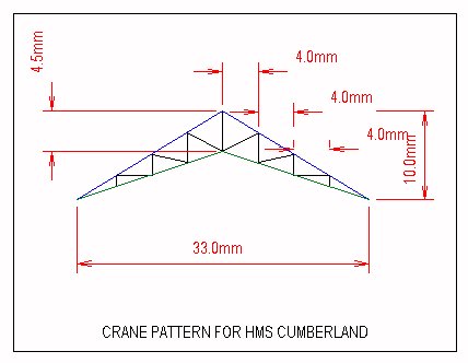
I made new cranes for this model from copper wire fixed with super glue gel. First I made a pattern (shown below) based on the kit supplied crane and a drawing in Raven and Roberts' British Cruisers. It is simplified some what but the end result looks very nice and has a good scale appearance. When you have drawn the pattern paste it down on a small piece of board or stiff card. Then obtain some fine copper wire (I got mine from and old radio) and stretch it straight by holding one end in a vice and pulling on the other with a pair of pliers. Just increase the pressure till you feel the wire give a little and its done. The wire should be now perfectly straight.
Take a length about 100mm long and bend it sharply in the middle so as to approximate the shape of the blue line in the drawing. Fix one end with a blob of Blu-Tack with the bend at the apex of the crane. Push the other end into position and fix it down with Blu-Tack. The wire should now match the shape of the blue line exactly. Next, comes the lower piece, represented by the green line. This must be bent and cut to fit exactly so this takes a little fiddling but is surprisingly easy. The components of this crane must not overlap one another as in the stretched sprue method. When the lower part is correctly shaped it can be glued to the upper part with a tiny blob of super glue gel applied with a pin (I have several ice cream sticks with pins mounted in the end for this. They make useful probes for manoeuvring small pieces into position as well.). You have to be careful to get the glue only on the upper surfaces of the crane assembly other wise it will stick to the pattern. This is quite easy as the gel does not run down around the components but stays put. The glue I use sets in about 10 seconds it is possible to move on with this rapidly, but you can sprinkle baking soda on to make the glue set instantly.
Once these two parts are glued together you can fill in the internal structure with small pieces of wire cut to size. I did the vertical components first, followed by the diagonal. I used baking soda to speed things up now and then but it does make the glued joint a bit lumpy, and these must be sanded and generally cleaned up before painting. The finished assembly is quite strong enough to handle this. You have to make four of these assemblies to construct the two cranes and they are simply cemented either side of the kit's crane engines. I made up a little jig from small blocks of wood and Blu-tack to ensure they lined up properly. If you wish you can add cross bracing between the halves after assembly (this is what I did) but they do look OK without. Overall, this is a good method for making finer structures like cranes and catapults for which no photo etched parts exist. Once I started each crane half took about 20min to make.
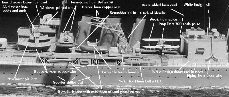
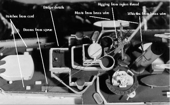
What remains now is general finishing off and detailing. The photographs below show the additions I made to complete the model. The photo etch set I used was the White Ensign Models Pre 1950s Royal Navy ship set and it just had enough rail for the entire ship. Not visible in the pictures are the grids I added on top of the funnels from copper wire.
In addition to using these colours I dry brushed over the anchor chains and handling gear with the camouflage grey to raise the detail (it would probably have been better to construct new details here). The ends of all gun barrels (including the pom-poms) were given a spot of black to give a tubular impression. The windows on the walrus were marked in with a laundry marking pen which worked quite well.
I pre painted the photetched railing while it was still on the fret and touched it up after installation. I used a brush for this and it worked out fine. I attached the rail with thinned white glue and brushed matt varnish over it when it had set to take away the glossy appearance.
The model was rigged with black nylon thread which was OK, but I think I will go back to using stretched sprue in future. I find the thread curls too much with the result that some of my rigging has a bend in it near the attachment points on the deck. Stretched sprue will glue on straighter. I used super glue gel and Zip Kicker accelerator for this job
Some Conclusions
Now that the project is finished I am quite happy with the completed model. This was my first
ever kit conversion and the modifications have changed it entirely. The finished result has all the
crispness and detail of modern Japanese ship kits. This was my intention from the outset. Its
impossible to deny that the Airfix Suffolk kit is a tired old offering compared to
modern kits but it can provide a lot of fun in the upgrading and Airfix ship kits in general provide
a dimensionally accurate base to start with. I did grow impatient with the project at times and
skipped a few things I should have done (like painting in the black boot top!), but overall the
finished article looks quite acceptable and now has pride of place on my shelf.