"The Old Navy" 1/700
scratchbuilt diorama
by John Leyland
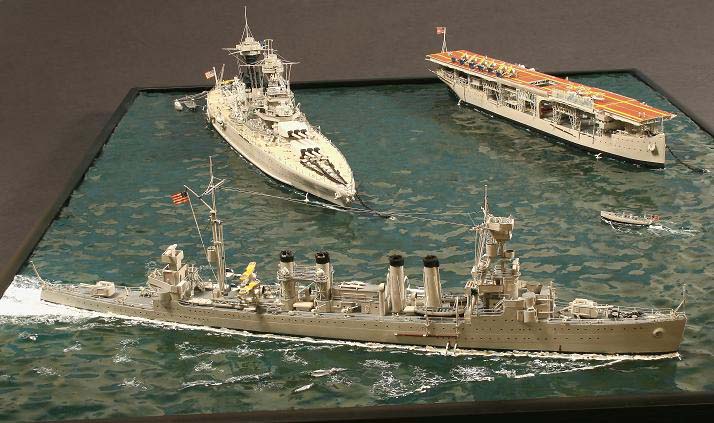
1/700 USS Marblehead CL-12 USS California BB-44 (scratchbuilt)
"The Old Navy" Part II
USS Marblehead CL-12 USS California BB-44
After completing the USS Langley model, I decided to expand the project
to include other ships from the late 1930's in a diorama. As always with
a ship diorama, the problem is to find an excuse to place several ships
close together without seeming too unrealistic. In this case, I decided
to depict an anchorage scene with two ships at anchor and a third steaming
past. I had always liked the look of the four stack light cruisers, and
the saga of Marblehead in the Asiatic Fleet at the begining of WWII made
her a natural choice. A cage mast battleship had been on my "want list"
for a long time, but I didn"t have a particular ship in mind. While I was
working on Marblehead, the book "Battleship Sailor" by Theodore Mason was
released detailing his adventures aboard California, so the choice was
made.
At the time the model was built, the only plans commercially available
for either ship were by Edward Wiswesser, who has a reputation for needing
careful correlation with other sources, but were still invaluable. Using
my experience from Langley, Marblehead was also built using the "eggcrate"
method as described in Part 1. During the construction, I had enough problems
with seams separating from applying excessive pressure that this was my
final model using this technique. I learned a lot fabricating the superstructure
from sheet styrene- one little piece at a time and throw away anything
that isn,t perfect and try again. The torpedo tubes, aircraft catapults,
ventilators, and boats are modified kit parts, everything else is scratch.
Being in the pre-photoetch age, I had to find a method to make "stairway"
type ladders. A large hemostat with coarse jaws was used to gently crush
a narrow strip of styrene to imprint a pattern on it which if gently stretched
would look fairly good. The photo showing the stern 1/3 of Marblehead has
a good example. I was surprised to learn that the light cruisers were only
70 ft. shorter than California.
Since the cage masts were the "limiting factor" of the California project,
they were built first. I was lucky to have found P.C.Coker's "Building
Warship Models", as this book contains a well thought out concept. Disks
of .020 styrene of the appropriate diameter were cut for the upper and
lower end of the mast and 32 equally spaced #80 drill holes were made around
the edge. In 1/700, there was not enough space to drill holes in the smaller,
upper disk, so it was notched like a gear instead. This would not be a
problem in 1/350, making the project much easier. Both disks had a second
ring of closely spaced holes drilled 1/8 in. inside the outer row to facilitate
cutting the center out of each disk to remove the center "handle" wire
when the project was complete. These disks were then epoxied to a piece
of coat hangar wire at the appropriate distance for the height of the mast
to support the mast during construction and serve as a sturdy handle. Two
essential details are important. First is that each wire runs 90 degrees
either clockwise or counterclockwise (ie. the two wires in the 12 o clock
hole in the lower base will run to the 3 o clock and 9 o clock holes in
the upper base). Second is that all the clockwise wires run in one layer
with all the counterclockwise wires on top of them- they are not interwoven!
This means that all parallel wires running in one direction are added to
the disks first. The wire threaded into the 12 o clock hole in the base
will run to the 3 o clock hole of the top. Remember that each hole will
receive two wires, so don't plug them with glue! Also, DO NOT GLUE the
lower wires when the inner layer is placed, as the outer layer will compress
them into the graceful curve of the mast as they are added, but the inner
layer must be FREE TO MOVE at one end for this to occur. I emphasize that
you don't have to pre-bend the wires, straight wires will produce the curve
by themselves as the outer layer is added if the are free to move at one
end.Therefore, I added the entire layer of 32 clockwise wires, gluing them
only at the top with cyano. As the outer layer of counterclockwise wires
were added, it was really neat to watch the curved shape take form. The
wire chosen has to be strong enough to compress the inner layer without
kinking it (or being kinked by it). I don't remember where I got the wire,
I was just lucky that my first choice worked well. As each wire of the
outer layer is placed, it can be glued at both ends. When the whole structure
is dry, several hoops have to be placed around the mast on the horizontal
plane. Fortunately, on the prototype the ends of these bands overlap consideraly
so they can be secures by clamps, so fine wire loops can be made, slipped
over the mast, and tightened with their ends overlapping to be glued. When
dry, excess wire above and below the disks must be removed. Toenail clippers
work well for this. In 1/700 and before photoetch, I did not add interior
platforms and ladders and these would not readily be seen anyway, but I
think they would be important in 1/350. When the deck plates where the
lower end of each mast will set were made, an appropriately sized circle
was cut out for the lower disk to recess into, leaving a level deck(and
allowing for a slight overhang in the lower end of the wires as they were
cut off below the lower disk after drying). The fore and maintop structures
were built hollow with a hole in the bottom, so neatness at the top of
the mast is not important as it can be hidden when it is inserted into
the top structure (make the mast a little long to allow for this). It took
me about six hours for the mainmast and my first try was successful. I
hope these instructions are clear, please email me if you have problems.
The hull of California was made using the "bread and butter" method
with sheets of .040 to .080 Plastruct. Before layers were glued, three
holes were drilled under A and Y turret location and in the center so that
bolts with large washers could be used to firmly compress the layers and
hold positive alignment during drying. After two weeks of drying, the hull
was scraped and sanded to shape and the armor belt added. The final upper
level of deck was added using Evergreen N gauge boxcar siding with the
holes cut to accept the lower ends of the masts. The turrets were a pain
to get matching size and angle, as I hadn't heard of resin casting yet.
The numbers on the "range clocks" were from a Woodland Scenics set of N
gauge railroad rub-on transfers. Note that they only go from 1 to 10! The
upper portion of the mainmast was painted Navy Blue, not black.
This model was awarded the "Most Popular Model" (now called "People's
Choice") at the 1984 IPMS USA National Convention in Atlanta.
"The Old Navy" Part
I
John
Leyland

© ModelWarships.com